Types of Compressor:

Types of Compressors:

A) Positive Displacement Compressors

A positive displacement compressor is a system that compresses the air by the displacement of a mechanical linkage reducing the volume (since the reduction in volume due to a piston in thermodynamics is considered as positive displacement of the piston).

Put another way, a positive displacement compressor is one that operates by drawing in a discrete volume of gas from its inlet then forcing that gas to exit via the compressor’s outlet. The increase in the pressure of the gas is due, at least in part, to the compressor pumping it at a mass flow rate which cannot pass through the outlet at the lower pressure and density of the inlet.

A – 1 ) Reciprocating Compressors

Reciprocating compressors use pistons driven by a crankshaft. They can be either stationary or portable, can be single or multi-staged, and can be driven by electric motors or internal combustion engines. Small reciprocating compressors from 5 to 30 horsepower (hp) are commonly seen in automotive applications and are typically for intermittent duty. Larger reciprocating compressors well over 1,000 hp (750 kW) are commonly found in large industrial and petroleum applications. Discharge pressures can range from low pressure to very high pressure (>18000 psi or 124 MPa). In certain applications, such as air compression, multi-stage double-acting compressors are said to be the most efficient compressors available, and are typically larger, and more costly than comparable rotary units. Another type of reciprocating compressor, usually employed in automotive cabin air conditioning systems, is the swash plate or wobble plate compressor, which uses pistons moved by a swash plate mounted on a shaft 

A linear compressor is a reciprocating compressor with the piston being the rotor of a linear motor.

This type of compressor can compress a wide range of gasses, including refrigerant, hydrogen, and natural gas. Because of this, it finds use in a wide range of applications in many different industries and can be designed to a wide range of capacities, by varying size, number of cylinders, and cylinder unloading. However, it suffers from higher losses due to clearance volumes, resistance due to discharge and suction valves, weighs more, is difficult to maintain due to having a large number of moving parts, and it has inherent vibration.

Reciprocating Compressors Schematic

A – 1 – 1 ) Diaphragm / Reciprocating Compressors

A diaphragm compressor (also known as a membrane compressor) is a variant of the conventional reciprocating compressor. The compression of gas occurs by the movement of a flexible membrane, instead of an intake element. The back-and-forth movement of the membrane is driven by a rod and a crankshaft mechanism. Only the membrane and the compressor box come in contact with the gas being compressed.

The degree of flexing and the material constituting the diaphragm affects the maintenance life of the equipment. Generally stiff metal diaphragms may only displace a few cubic centimeters of volume because the metal cannot endure large degrees of flexing without cracking, but the stiffness of a metal diaphragm allows it to pump at high pressures. Rubber or silicone diaphragms are capable of enduring deep pumping strokes of very high flexion, but their low strength limits their use to low-pressure applications, and they need to be replaced as plastic embrittlement occurs

Diaphragm / Reciprocating Compressor Schematic

A – 1 – 2 ) Single Acting / Reciprocating Compressors

A single-acting compressor is a type of air compressor that uses only one end of the piston for the suction and compression. So the first stroke of the piston sucks the air inside the compressor while the air compression occurs in the second stroke. Piston goes down: air draws in. Piston goes up: air is pushed out.

Single-Action/ Reciprocating schematic

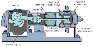
A -1- 3 ) Double Acting / Reciprocating Compressors

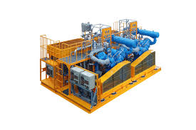
Double acting compressors are generally designed for rugged 100% continuous operations.  Dubbed the workhorse of the compressor family, they are also known for their long service life.  They are commonly used in high pressure services in multistage styles and can come in lubricated and non-lubricated configurations.   With the dual compression, slow speed and inter-cooling, it makes this type of air compressor very proficient in making compressed air.

Double-Action / Reciprocating schematic
Reciprocating Air Compressor Package

A – 2 ) Rotary Compressors

Rotary compressors are a subset of positive displacement machines. Rotary compressors have a number of features in common even though there are differences. A rotary screw compressor is a type of air compressor that uses two rotating screws (also known as rotors) to produce compressed air. Rotary screw air compressors are clean, quiet and more efficient than other compressor types. They are also supremely reliable, even when used continuously.

Rotary compressors as a group comprise the balance of the positive displacement machines. This group of compressors has several features in common despite differences in construction. Probably their most important feature is the lack of valves as used on the reciprocating compressor. The rotary compressor is lighter in weight than the reciprocating compressor and does not exhibit the shaking forces of the reciprocating type, making the foundation requirements less rigorous. Even though rotary compressors are relatively simple in construction, the physical design can vary widely. Both multiple- and single-rotor construction is found. Rotor design is one of the main items that distinguishes the different types. Size and operating range are other elements unique to each type of rotary compressor. The following sections cover some of the more common rotary compressors in detail.

Vane / Rotary Compressor Scheme
Screw / Rotary Compressor Scheme
Scroll / Rotary Compressor Schematic
Liquid Ring / Rotary Compressor Schematic
Lobe / Rotary Compressor Schematic

A – 2 – 1 ) Vane / Rotary Compressors     (Eccentric rotary-vane)

Rotary vane compressors consist of a rotor with a number of blades inserted in radial slots in the rotor. The rotor is mounted offset in a larger housing that is either circular or a more complex shape. As the rotor turns, blades slide in and out of the slots keeping contact with the outer wall of the housing.Thus, a series of increasing and decreasing volumes is created by the rotating blades. Rotary vane compressors are, with piston compressors one of the oldest of compressor technologies.

The Rolling piston in a rolling piston style compressor plays the part of a partition between the vane and the rotor.Rolling piston forces gas against a stationary vane.Two of these compressors can be mounted on the same. In refrigeration and air conditioning

Vane / Rotary Compressor Scheme

A – 2 – 2 ) Scroll /  / Rotary Compressors

A scroll compressor, also known as scroll pump and scroll vacuum pump, uses two interleaved spiral-like vanes to pump or compress fluids such as liquids and gasses. The vane geometry may be involute, archimedean spiral, or hybrid curves. They operate more smoothly, quietly, and reliably than other types of compressors in the lower volume range. Due to minimum clearance volume between the fixed scroll and the orbiting scroll, these compressors have a very high volumetric efficiency.

These compressors are extensively used in air conditioning and refrigeration because they are lighter, smaller and have fewer moving parts than reciprocating compressors and they are also more reliable.

Scroll / Rotary Compressor Scheme

A – 2 – 3 ) Liquid Ring / Rotary Compressors


The liquid-ring pump compresses gas by rotating a vaned impeller located eccentrically within a cylindrical casing. Liquid (often water) is fed into the pump, and by centrifugal acceleration forms a moving cylindrical ring against the inside of the casing.

High pressure liquid ring compressors deliver reliable, proven performance for toxic, explosive, and corrosive gasses in oil & gas, petrochemical, and chemical applications including flare-gas recovery and vinyl chloride monomer (VCM) recovery.

Liquid Ring / Rotary Compressor Scheme

A – 2 – 4 ) Screw / Rotary Compressors


A rotary-screw compressor is a type of gas compressor, such as an air compressor. These compressors are common in industrial applications and replace more traditional piston compressors where larger volumes of compressed gas are needed, e.g. for large refrigeration cycles such as chillers, or for compressed air systems to operate air-driven tools such as jackhammers and impact wrenches. For smaller rotor sizes the inherent leakage in the rotors becomes much more significant, leading to this type of mechanism being less suitable for smaller compressors than piston compressors.

rotary screw compressor

A – 2 – 5 ) Lobe / Rotary Compressors


Lobe type rotary air compressor, in its simplest form, consists of two rotor lobes rotating in an air-tight casing which has inlet and outlet ports.There are many designs of wheels, but it generally has two or three lobes.The lobes are so designed that they provide air tight at the point of their contact.The arrangement of lobe type rotary air compressor , The mechanical energy provided to one of rotors from external source, while the other is gear driven from the first. As the rotor rotates, the air at atmospheric pressure is trapped in the pockets formed between the lobes and casing.The rotary motion of the lobes delivers the entrapped air into the receiver. Thus more and more flow of air into the receiver increases its pressure. Finally the air at higher pressure is delivered from the receiver.

Lobe / Rotary Compressor Scheme

B) Dynamic Compressors:   (Air bubble compressors)

Dynamic compressors operate by continuously increasing the momentum of a gas as it flows through them and do not rely on a trapped volume. Examples of compressors of this type include centrifugal (also called radial) compressors, axial compressors, and mixed flow compressors.

The dynamic compressors are also known as a trompe. A mixture of air and water generated through turbulence is allowed to fall into a subterranean chamber where the air separates from the water. The weight of falling water compresses the air in the top of the chamber. A submerged outlet from the chamber allows water to flow to the surface at a lower height than the intake. An outlet in the roof of the chamber supplies the compressed air to the surface.

B – 1 ) Centrifugal / Dynamic Compressors:

A single-stage centrifugal compressor is defined as the combination of one impeller with its associated inlet guide vane and diffuser. Velocity is converted into pressure within the diffuser and then further increased as the gas passes through the volute.

  • Single Stage Centrifugal Compressors
  • Integrally Geared Centrifugal Compressors


B – 1 – 1 ) Single Stage Centrifugal Compressors:

A single-stage centrifugal compressor is defined as the combination of one impeller with its associated inlet guide vane and diffuser. Velocity is converted into pressure within the diffuser and then further increased as the gas passes through the volute.

Single Stage / Centrifugal Compressor Scheme

B – 1 – 2 ) Integrally Geared Centrifugal Compressors

Integrally geared compressors are multi-shaft machines. Several pinion shafts with one or two impellers each are arranged around a central bull gear. For each pinion shaft a perfect combination of shaft speed and impeller size can be realized. All impellers are of overhung design and can be fitted with adjustable inlet guide vanes in front of each impeller. Inter-stage cooling of the gas stream can be done after each impeller discharge. The combination of these features allows for high volume flows, outstanding energy efficiency even under part load, all in a compact design.

Integrally geared / Centrifugal Compressor Scheme

B – 2 ) Axial / Dynamic Compressors

Axial compressors are dynamic rotating compressors that use arrays of fan-like airfoils to progressively compress a fluid. They are used where high flow rates or a compact design are required.

The arrays of airfoils are set in rows, usually as pairs: one rotating and one stationary. The rotating airfoils, also known as blades or rotors, accelerate the fluid. The stationary airfoils, also known as stators or vanes, decelerate and redirect the flow direction of the fluid, preparing it for the rotor blades of the next stage.[1] Axial compressors are almost always multi-staged, with the cross-sectional area of the gas passage diminishing along the compressor to maintain an optimum axial Mach number.

Axial / Dynamic Compressor Scheme